

Leon Odendaal is a Mechanical Engineer at Beruseal, holding a Bachelor of Engineering degree in Mechanical Engineering. He works on pressure-containing mechanical equipment, mechanical integrity, and field engineering, with a focus on the design and verification of engineered mechanical enclosures for on-line leak repair.


Loads Introduced By The Repair
Internal pressure is the primary design load. Less obviously, installing the enclosure modifies the pressure boundary and introduces additional load paths that are typically well understood but should always be considered in the design approach.
Extension of the effective pressure area.
On an enclosure fitted over a flanged joint, the existing studs were sized for internal pressure acting over the area bounded by the gasket, together with the load required to maintain gasket compression. Once the enclosure encloses the flanges and sealant fills the intervening space, pressure may act over an area extending to the flange outside diameter. The pressure is unchanged; the area, and therefore the separating force and the resulting stud tension, are not. Since the extent of sealant penetration cannot be verified externally, the design must be based on the larger area.
Function of the strong-back.
Where the existing bolting has insufficient capacity for the increased separating force, the design response is external restraint, or replacement of the studs with higher-strength material under a controlled hot bolting procedure. The strong-back is not a supplementary fitting. It is the load path provided for a pressure area against which the original joint was never designed.
Net axial thrust and axial restraint.
Where the pressurised areas at each end of an enclosure are unequal, a net axial thrust develops which the enclosure and its attachment to the component must react. Where the defect may progress to full circumferential separation, the enclosure may be required to carry the full end load of the line. ASME PCC-2, Part 3, Article 306, “Mechanical Clamp Repair”, requires a locking mechanism or strong-back where longitudinal forces are to be restrained, and states that friction shall not be relied upon to hold together damaged or separated components in flammable, toxic or tissue-damaging service, or in the creep range, in the absence of a documented risk analysis. Axial restraint is accordingly a design requirement established at the outset, not a field modification introduced later.
Installation loads.
Bolt preload is reacted as contact pressure on the component wall and persists for the life of the repair. Sealant injection pressurises the annulus, and Article 306 requires the possibility of inward collapse of the clamped component under annulus pressure to be considered. Fit-up loads and the bolt tightening sequence determine the uniformity of the initial seal contact.
These loads are identified at the design stage and are normally recorded on the design data sheet. The loads described in the remainder of this article can typically be missed if not specifically identified during the repair scope.
Loads Transmitted from the Piping System
An enclosure is not installed on an isolated pipe. It is installed into a piping system, and it inherits the load state existing at the landing area. Classifying what it inherits is worthwhile, because the three classes behave differently:
Sustained loads are load-controlled. The weight of pipe, contents and insulation, and the bending moments they produce, do not diminish as the enclosure or the component deforms.
Displacement-controlled loads arise from thermal expansion, contraction and support movement. They are self-limiting and relax as deformation occurs, but they are fully capable of unseating a seal before they do so.
Occasional loads are transient and impulsive: fluid transients, wind and seismic events.
Thermal expansion and restraint.
An enclosure is a locally stiff element installed on a line designed to accommodate movement. It stiffens the length it covers, transferring flexibility demand to the adjacent sections, and it may act as an unintended restraint. Article 306 requires consideration of differential expansion and contraction, and of the effect on the flexibility of the pipe or component. It further identifies operating and residual stresses arising from constrained differential expansion as a cause of leakage at the clamp. Such leakage is commonly attributed to the sealant when the governing mechanism is mechanical.
The position of the enclosure relative to existing restraints is as significant as its size. An enclosure installed mid-span, with flexibility available on both sides, presents a different problem to the same enclosure installed close to an anchor or a seized guide, where the two restraints act in combination. Site records seldom identify which condition applies.
A second thermal effect occurs within the enclosure itself. During heat-up the enclosure body and the component do not attain temperature simultaneously, nor expand equally. Article 306 accordingly notes that on insulated lines the enclosure may also be insulated in order to minimise differential expansion.
Sustained weight and bending.
The enclosure is installed within a span already carrying a bending moment from the weight of pipe, contents and insulation. Support locations were established for the original configuration, not for a repair introducing concentrated mass within the span. Support settlement, a spring hanger operating outside its working range, or a seized guide will each redistribute moment onto the repair, generally
Bending Moment and Non-Uniform Seal Contact Pressure
Axial force and bending moment act on an enclosure in fundamentally different ways, and the distinction determines which check governs.
An axial force is reacted approximately uniformly across a correctly proportioned enclosure. A bending moment is not. It produces rotation of the enclosure relative to the component, which redistributes seal contact pressure along the length of the enclosure: contact pressure increases at one end and decreases at the other.
Both conditions are adverse. At the loaded end, contact pressure on the component wall exceeds the design value, at a location where wall thickness has already been reduced. At the unloaded end, contact pressure may fall below the minimum required by the sealing element, and leakage initiates there. This mechanism accounts for enclosures that seal satisfactorily on installation and develop leakage at one end after a period in service, with no corresponding change in process conditions.
The consequence for design review is that the two components are assessed against different criteria. The pipe is assessed against allowable stress. The enclosure is assessed against maintenance of seal contact pressure over its full length. A bending moment may satisfy the first criterion while failing the second.
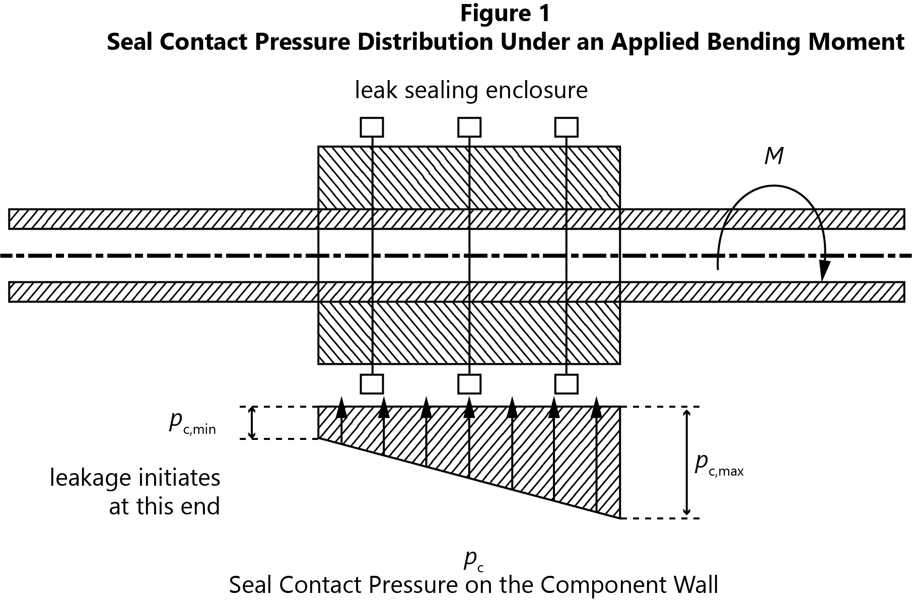
NOMENCLATURE. M = bending moment applied by the piping system; pc = seal contact pressure on the component wall; pc,min = minimum contact pressure required by the sealing element.
NOTES. (1) The enclosure rotates relative to the component under M. (2) Contact pressure increases at one end and decreases at the other. (3) Leakage initiates where the contact pressure falls below the minimum required by the sealing element. (4) Symbols are defined for this figure only and are not Code symbols.
Defining the Enclosure Load Envelope
Shell and tube heat exchangers designed to API 660 are supplied with tabulated allowable nozzle forces and moments, and the piping designer is required to demonstrate that the connected system remains within them. An enclosure requires an equivalent envelope: the combination of forces and moments beyond which the sealing element, the bolting or the component wall will not perform as intended.
No published envelope exists, because the enclosure is designed for a single defect. Establishing it, recording it, and verifying the connected system against it is therefore part of the repair design. Where a pipe stress model is available, the forces and moments at the repair location may be extracted directly. In the more common case where no model exists, the envelope must be derived from the geometry, the support arrangement and the operating history.
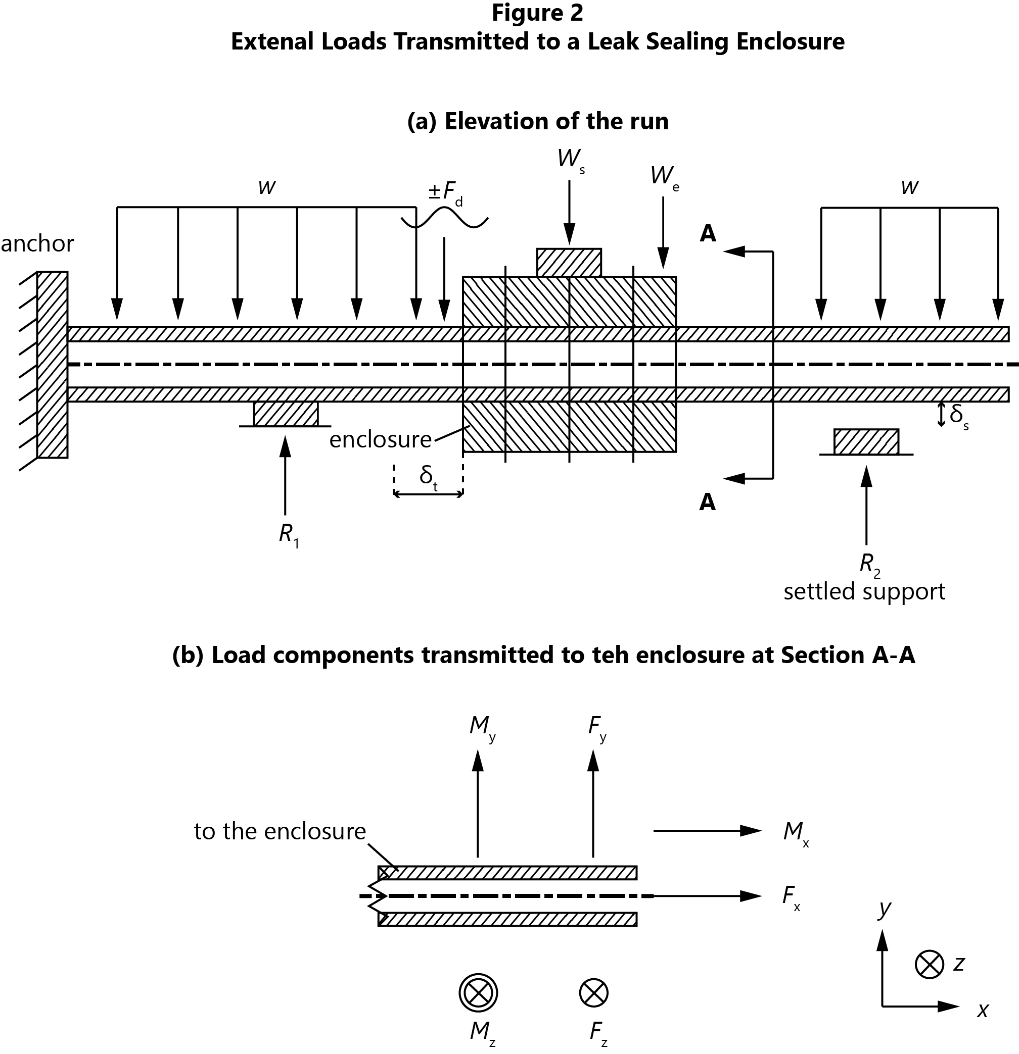
NOMENCLATURE. w = weight of pipe, contents and insulation, per unit length; Ws = superimposed load applied after the repair (insulation, cladding, ice accretion, scaffolding and subsequent attachments); We = weight of the enclosure, the entrapped fluid and the annular space material; ±Fd = cyclic and impulsive load from vibration and fluid transients; R1, R2 = support reactions; δs = support settlement; δt = differential thermal expansion between the enclosure and the component; Fx, Fy, Fz = force components transmitted at Section A–A; Mx, My, Mz = moment components transmitted at Section A–A.
NOTES. (1) A single arrowhead denotes a force and a double arrowhead a moment; a circled cross denotes a vector acting into the plane of the figure; ± denotes an alternating load. (2) Fx includes axial thrust from constrained thermal expansion, the anchor being the restraint against which it develops. Fy and Mz arise from sustained weight, span bending and support settlement. Fz and My arise from wind, seismic and out-of-plane transients. Mx arises from torsion where the run changes direction. (3) δt develops because the enclosure and the component do not reach temperature together or expand equally, and is the mechanism behind leakage attributed to the sealant when the cause is mechanical. (4) The enclosure load envelope is the combination of these components beyond which the sealing element, the bolting or the component wall will not perform as intended. (5) Loads reacted by the host component are shown in Figure 3. (6) Loads are shown schematically and are not to scale. (7) Symbols are defined for this figure only and are not Code symbols.
Occasional and Transient Loads
Steady loads are the more readily quantified. Cyclic and impulsive loads accumulate damage and are the more frequently omitted.
- Vibration. Reciprocating machinery, flow-induced vibration and adjacent control valves impose cyclic loading. A bolted joint subject to vibration may lose preload, with a corresponding reduction in seal contact pressure. The customary field response to weepage is further tightening, which restores the seal by increasing contact pressure on a wall that has undergone additional corrosion in the interval. The two events are separated by sufficient time that the connection between them is rarely made.
- Fluid transients. Fluid hammer and liquid slug are identified in Article 306 among the transient loads applicable to structural clamps. They are impulsive, frequently undocumented, and are transmitted to the enclosure as bending moment as often as axial force, since they act on the changes of direction adjacent to the repair rather than on the repair itself.
- Thermal cycling. Start-up, shutdown and trip conditions cycle the differential expansion described above. An enclosure sealing satisfactorily at operating temperature may leak on cool-down. A line cycling weekly accumulates substantially more load reversals within two years than is generally assumed for a repair designated temporary.
Article 306 requires the coincident maximum and minimum pressures and temperatures to be considered. Each load class may satisfy its individual check while the combination governs: a cold start at maximum differential expansion, coincident with a pressure transient, on a support that has settled since installation. The design case is the worst credible combination. Identifying which combinations are credible requires operating input rather than calculation.
Environmental and Accumulated Loads
These loads are frequently discounted on the basis that the repair is temporary. Repairs commonly remain in service for years, and that basis does not remain valid.
- Wind and seismic. Article 306 identifies both for structural clamps. A large enclosure on an elevated line presents projected area to wind loading and adds mass to the seismic response of the run.
- Subsequently applied loads. Insulation and cladding, ice accretion, scaffolding tied to the enclosure, and adjacent repairs are all reacted by the same weakened component, and none formed part of the original design basis.
- Continuing degradation. The damage mechanism responsible for the leak generally remains active. All of the loads above therefore act on a component of decreasing capacity.
Loads Imposed on the Host Component
Loads transmitted from the enclosure into the component receive the least attention and have the least available margin, since the component is by definition degraded.
Article 306 requires the clamped component to be examined to confirm sufficient wall thickness at the clamp contact points to carry the pressure and structural loads already present in the component, together with the additional loads imposed by the clamp. Thickness readings taken at the defect alone do not satisfy this requirement. The landing areas require separate measurement.
Over the installed life, the component wall carries:
- Contact pressure from bolt preload. Landing areas are rarely truly circular. Ovality, weld caps, the footprint of a previous clamp and local wall loss result in initial contact on high spots, so that an intended continuous contact band is realised as discrete patches at contact pressures substantially above the nominal value. Local bending and shear at these patches may govern in preference to membrane behaviour. This is the basis for manufacturing enclosure components with undersized bores and machining them on site to measured dimensions.
- Weight of the repair. Article 306 identifies the enclosure, the entrapped leaking fluid and the annular space material as a design load, reacted by the section that has lost wall thickness.
- Elevated temperature of encapsulated components. Process fluid contact, or the insulating effect of the enclosure, may raise the temperature of encapsulated bolting to the point of yielding. Bolting adequate on an exposed flange is not necessarily adequate once enclosed, and the condition is not externally apparent.
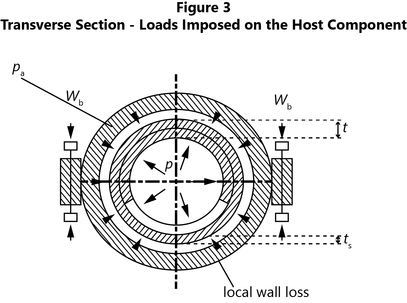
NOMENCLATURE. P = internal design pressure; pa = sealant annulus pressure; Wb = bolt preload, reacted as contact pressure; t = nominal component wall thickness; tr = reduced wall thickness at the area of loss.
NOTES. (1) The component wall carries the loads already present in it, together with the additional loads imposed by the enclosure. (2) The annulus pressure acts inward and is resisted by the reduced section. (3) Contact pressure from the bolt preload concentrates at the seal lands and at high spots on an out-of-round surface. (4) Symbols are defined for this figure only and are not Code symbols.
Data Required Before Design
The quality of every load assessment above depends on the site data supporting it. The following materially affect the design:
- Temperature range and cycling behaviour of the line, in addition to the operating temperature.
- Location and condition of the nearest anchors, guides and supports, and the distance from the repair to each.
- Wall thickness at the landing areas, measured separately from the defect, with sufficient readings to establish out-of-roundness.
- Credibility of progression to full circumferential separation, which determines whether the enclosure is classified as structural.
- Presence of vibration or transients, and availability of a pipe stress model from which repair loads may be extracted.
- Whether the enclosure is to be insulated, and what is likely to be attached to it subsequently.
- Which conditions occur coincidentally, since the governing case is a combination.
None of these requires significant time to establish. All become more difficult once the enclosure is installed, and several cannot be established at all once the enclosure covers the surface requiring measurement.
