

Leon Odendaal is one of the mechanical engineers at Beruseal, with a strong background in both asset integrity management and advanced non-destructive testing (NDT) techniques.
Leon is a highly valued member of our engineering team. He offers a unique, holistic perspective on industrial plant maintenance and leverages his technical experience to troubleshoot and implement reliable, long-term integrity solutions.
Lorem Ipsum

Lorem Ipsum
Defining the Repair Scope of Damaged Pressurised Equipment
In any pressurised system, damage or leakage of components represents a potential integrity and safety threat to any operational personnel and equipment in the vicinity.
Within the industry of on-line leak sealing throughout the years there were a handful of infamous incidents that occurred due to the insufficient focus placed on properly scoping the repair and/or designing & manufacturing an appropriate OLSD.
Defining the repair scope is therefore the critical first step in ensuring that subsequent repair activities are safe, technically sound, and compliant with any applicable repair and construction codes and standards. A well-defined scope provides a clear understanding of the problem, the extent of damage, and the boundaries of the intended repair. Without a clear scope, the repair efforts risk being temporary, incomplete, or outright unsafe.
When defining the scope for the repair of pressurised equipment it’s always imperative that the process aligns with the requirements of recognized industry repair codes such as ASME PCC-2, API 510, and/or API 570, all of which emphasize the need for documented engineering evaluation before repair work begins.
The installation of on-line leak sealing devices may not always be the most appropriate solution for the repair scope at hand. The selection of the repair methodology should always balance safety, service life, and efficiency requirements with the production and operational needs at the time the defect is scoped.
In addition to the need for a quick repair solution, these On-line Leak Sealing Devices should almost always be installed in a “cold-work” environment due to the actively leaking nature of the defects these are typically applied to, which typically means these devices are bolt-on solutions. A combination of a bolt-on and welded enclosures may be a valid permanent solution should the enclosure conform to both repair methodologies.
The following points should always be considered when scoping for on-line leak sealing devices:
Problem Confirmation and Data Collection:
The first stage in defining a repair scope is to confirm the existence and nature of the problem. This involves positively identifying the affected equipment using its tag number, location, and service description. Accurate operational data, including pressure, temperature, fluid composition, process upset cycles and flow conditions must be recorded, as these parameters directly influence repair feasibility and safety considerations for the effective installation of an OLSD.
A thorough review of the equipment’s history should follow, including past inspections, corrosion monitoring results, and any previous repairs. Collecting this background information helps establish whether the defect is new or recurring, and whether underlying issues such as process upsets or design weaknesses may be contributing factors. Immediate safety must also be evaluated at this stage. If the equipment cannot be safely inspected in its current condition, proper scoping for an OLSD would likewise not be feasible, and consequently, the installation of an OLSD would be unsafe.
Damage Characterization:
Once the problem is verified, the next step is to characterize the damage in both type and extent. This is achieved through a combination of visual inspection and non-destructive examination (NDE) techniques. The technique ultimately utilized will depend on the nature of the defect and the operational status of the affected equipment. Common techniques include ultrasonic thickness testing (UT), dye penetrant testing (PT), magnetic particle inspection (MPI), and radiographic testing (RT).
The goal is to define measurable parameters; depth, length, area, and location of the defect, as well as the nature of the defect; gasket/packing weep, through-wall pinhole, flange joint leak, weld washout, general wall thinning, and different kinds of cracks, rather than relying on only qualitative descriptions.
Equally important is identifying the damage mechanism, which could range from general corrosion and erosion to thermal fatigue, stress corrosion cracking, or mechanical impact. Understanding how the damage occurred helps determine whether it is stable or actively progressing, influencing both the urgency and design of the repair. The outcome of this stage should be a factual, quantifiable description of the defect that will serve as an engineering input to which the repair method will be chosen.
Establishing Repair Boundaries:
With the defect characterized, the repair boundaries must be clearly established. These boundaries define the physical extent of the repair area, including the length and circumference of pipe or the section of vessel to be addressed. System boundaries are also identified to determine where isolation or pressure control may be required, and which adjacent components may be affected.
Operational boundaries, such as allowable pressure, temperature, process fluctuations or flow conditions during repair, are defined to ensure that the repair can be performed safely, especially for installations of On-line Leak Sealing Devices. Material boundaries are likewise identified, including details of base metal, welds, linings, and coatings that may influence material compatibility or bonding with sealants and clamps. Defining these limits ensures that everyone involved understands the scope of work and that no assumptions are made in the field.
Specifically for on-line leak sealing devices, clear and accurate dimensional analysis of the total repair boundary must be communicated to the design office, as this forms the basis for the effective construction, installation, and sealing of the OLSD. Cleaning and surface profiling the expected landing areas for the leak sealing device is recommended to ensure accurate measurements are being designed and manufactured to.
Risk Evaluation and Engineering Requirements:
The next phase involves evaluating the risks associated with the damage and determining the level of engineering effort required. Risk assessment considers the potential consequences of failure, such as personnel injury, environmental release, or production loss, alongside the likelihood of further degradation.
The outcome of this evaluation categorizes the repair as temporary, permanent, or requiring a formal design review under a recognized code. For example, a minor leak at a flange gasket may be addressed by a clamp or sealant injection with minimal engineering input, whereas a through-wall crack in a pressure boundary could necessitate a full structural analysis and code re-rating of the total piping spool. The complexity of the defect dictates the qualifications of personnel involved, from certified inspectors to pressure equipment engineers, ensuring that the repair is proportional to the associated risk.
Defining Functional and Performance Requirements:
Every repair must have clear functional objectives and measurable performance criteria. These requirements translate the engineering intent into specific targets. The primary function may be to restore pressure containment, provide structural reinforcement, or temporarily seal a leak until shutdown.
Performance parameters such as design pressure and temperature as well as expected service life are defined to guide design decisions. For instance, a temporary clamp designed for a three-month service at 10 bar and 100°C will differ significantly from a long-term enclosure rated to full design conditions. Additional considerations include accessibility for inspection, corrosion monitoring, and environmental constraints such as restricted access or hot work prohibitions. These requirements ensure that the chosen method performs reliably within its intended limits.
Repair Method Selection and Justification:
Based on the defined scope and performance requirements, a suitable repair method can be selected. Options typically include bolted mechanical clamps (OLSD), composite wraps, welded sleeves, or section replacement. Each method has specific design and application limits well defined in ASME PCC-2, with ISO 24817 specifically expanding on non-metallic repairs.
The selection process must consider compatibility with the damaged material, process conditions, and the identified damage mechanism. The engineering justification should clearly document why the chosen method is appropriate, how it satisfies performance requirements, and what contingencies exist should site conditions differ from expectations. This documentation ensures transparency and traceability for both internal reviews and regulatory compliance.
Documentation and Communication:
Effective communication and documentation are vital to ensuring that all stakeholders share a consistent understanding of the repair scope. The repair package should include inspection results, sketches or photographs, the proposed method, performance requirements, and any limitations or precautions.
Formal approval is typically required from engineering, inspection, safety, and operations representatives. Pre-job meetings or toolbox talks should be conducted to review hazards, confirm scope boundaries, and reinforce stop-work authority. The final documentation should be linked to the organization’s Management of Change (MOC) system, ensuring full traceability of the repair decision and facilitating future audits or re-inspections.
In conclusion, defining the repair scope is as vital as executing the repair itself. It forms a typically viewed unorganised reactive maintenance response into a structured, risk-based process that ensures every repair is fit-for-purpose, traceable, safe and compliant.
By systematically evaluating the problem, characterizing the damage mechanism, setting clear boundaries, assessing risk, defining performance targets, and documenting the process, organizations can ensure that their repairs not only restore integrity but also maintain the safety and reliability of the entire pressure system.
When properly and effectively applied, this approach ensures regulatory compliance under the repair standard ASME PCC-2, referencing API 510, and API 570, while ensuring operational continuity with protecting personnel and assets from harm.
The next section expands on the specific processes involved when a mechanical clamp or OLSD is selected as the repair method for the defect at hand.
Design and Engineering Requirements
The definition of on-line leak sealing is the specialized repair technique that allows continued operation of pressurized systems while containing active leaks. The practices of on-line leak sealing often requires the use of bolted mechanical clamps often referred to as On-line Leak Sealing Devices. As previously noted, the nature of this repair technique requires that the design of these devices ensures safety, mechanical integrity, and compliance with recognized standards under live service conditions.
This section outlines the fundamental engineering principles, design requirements, material selection criteria, and validation steps that underpin the safe manufacture and use of on-line leak sealing devices. The basic principles of pressure vessel design, load paths, bolted joint integrity, and material compatibility, as typically defined in ASME BPVC Section VIII and ASME PCC-2 are used for the design of these devices.
The ASME equivalent specifications are specifically referenced as these are typically regarded as the industry standard for designing OLSD’s, however any equivalent internationally accredited pressure vessel construction codes such as the EN 13445 series, PD5500, etc. would also be applicable for use in designing OLSD’s as these will generally encapsulate the same engineering principles showcased in ASME BPVC Section VIII.
The foundational concepts for designing OLSD’s:
The primary purpose of an on-line leak sealing device is to safely and temporarily restore pressure containment without isolating or depressurizing the system. These devices are typically used for leaks at flanges, valves, fittings, or small through-wall defects where system shutdown is impractical or unsafe.
General wall thinning and circumferential crack-like defects may be repaired using on-line leak sealing devices, provided sufficient information about the defect characteristics is available to accurately determine the expected repair lifetime. However, defects resulting from stress corrosion cracking (SCC), as well as longitudinal or multi-directional cracks, present a different challenge. While an OLSD can be installed over these defects to temporarily contain the leak, a permanent repair addressing the underlying failure mechanism must be implemented as soon as possible.
While designs vary, most on-line leak sealing systems share common standard features, as stated below:
Pressure-retaining enclosure or clamp that encloses the entire leak area.
Sealing element or injectable compound that provides the leak barrier.
Fastening system (e.g., bolting or banding) to apply and maintain sealing pressure.
Injection fittings and ports for introducing sealants under controlled pressure.
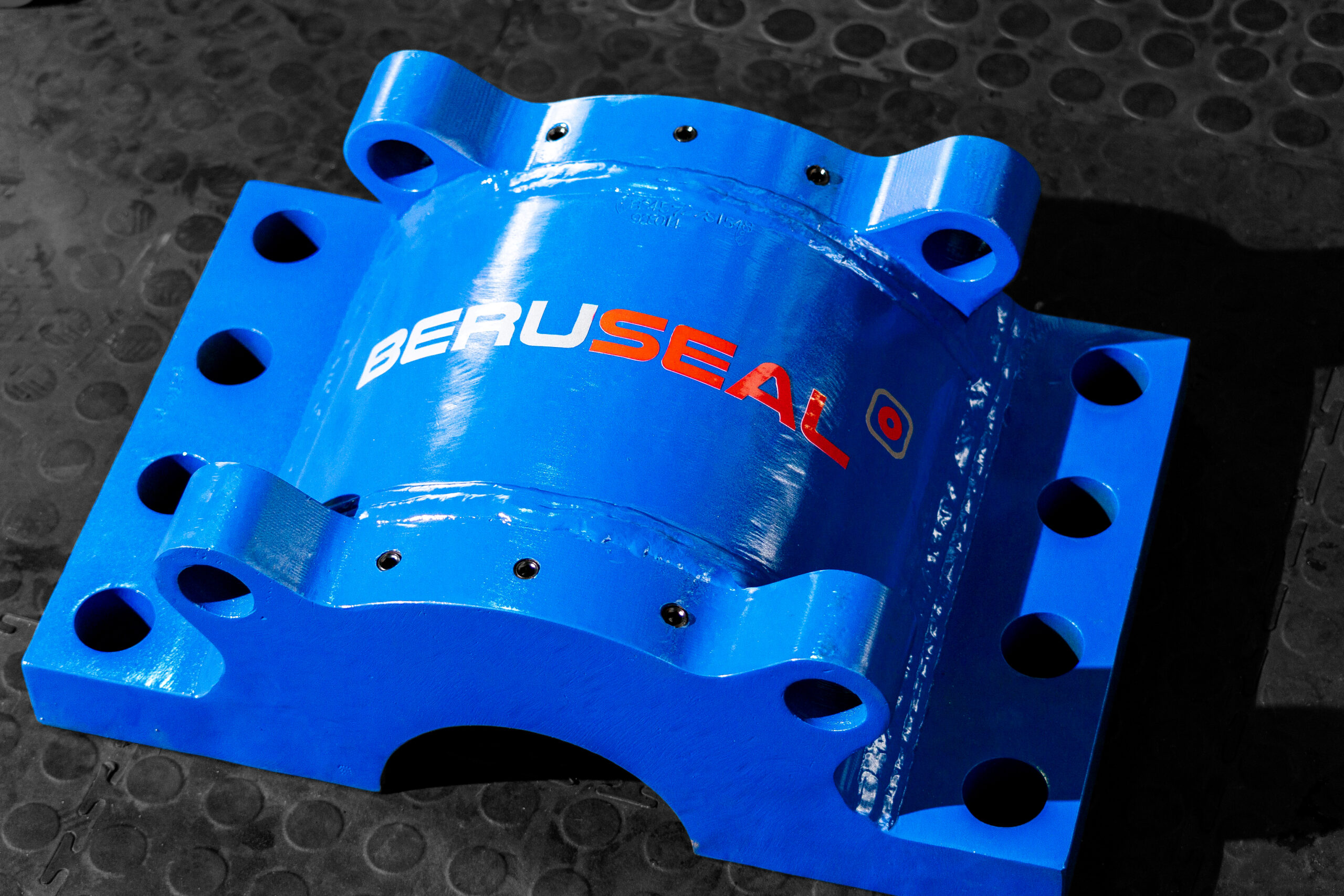
Friction clamps, hooks or shear lips to ensure component axial integrity in the event of circumferential failure of the component underneath the OLSD.
Caulking/peening grooves or lips on the lading bores to provide a final sealing interface
Addition of lifting lugs for large and heavy enclosures to assist installation.
The effectiveness of the device depends on both the mechanical strength of the enclosure and the compatibility and performance of the sealing medium.
Design Philosophy and Guiding Standards:
All on-line sealing devices should be designed as pressure-containing components in accordance with the applicable pressure vessel construction code and adhering to sound engineering principles where possible. The device must safely withstand internal pressure, temperature, and mechanical loads without relying on the damaged section of the host equipment for strength.
Although briefly mentioned earlier, the design and engineering decisions for designing on-line leak sealing devices should always be rooted or conforming to recognized industry construction standards, as per the following:
ASME PCC-2 – Repair of Pressure Equipment and Piping
ASME BPVC Section VIII Division 1 – Rules for construction of pressure vessels
These standards establish minimum safety margins, testing requirements, and validation methods for temporary pressure-retaining repairs.
However, because on-line leak sealing devices can become quite bespoke due to the geometrical limitations associated with operational installations, certain pressure containing elements can and will fall outside the specific geometrical scopes of the construction standards as listed. In these cases, following sound engineering practices and first principal design evaluations with incorporating the safety methodologies implemented in the construction codes is vital in these cases to ensure safety.
The following references can be used to assess geometries falling outside the typical geometric scope of the recognized industry construction standards:
ASME BPVC Section VIII code cases – Approved, non-mandatory alternatives that provide guidelines for the design, construction, and certification of pressure vessels
Finite Element Analysis (FEA) – ASME BPVC Section VIII Division 2 – Rules for construction of high-pressure vessels
Roark’s Formulas for Stress and Strain – A comprehensive reference book and a collection of tabulated formulas for analysing stress and strain in mechanical and structural components under various loads.
These assist in optimising pressure baring elements without unnecessarily over-engineering the enclosures, however these approaches may typically increase the design lead time. This would typically be supported by the need to optimise the weight or fabrication cost of the enclosure.
The design limits must reflect the maximum credible operating conditions rather than nominal ones. When detailed design information is unavailable, a safety margin, typically 10–25%, should be added to the rated operating pressure and temperature to account for possible process variations.
Enclosure Structural Design Requirements:
The enclosure and subsequent supporting elements must always be structurally capable of carrying all imposed loads, including internal pressure, external mechanical forces, differential thrust forces when applicable, axial separation load capacity, as well as sealing bolt tension. All of these should be evaluated independently of the defective base material. The design should ensure that pressure loads are transmitted through the clamp body rather than the weakened wall of the equipment along with evaluating the external pressure load on the compromised component.
Key design considerations include:
Hoop and axial stress calculations based on internal pressure for all pressure baring components
Verification of flange and shell thicknesses for separation force load transfer.
Stress assessment of combined load cases should axial restraints be connected directly to pressure containing elements.
Mechanical stability under combined loads cases (pressure, temperature, and weight).
Allowance for local shell deformation and ovality.
Corrosion Allowance based on service medium, clamp material and service life.
For complex geometries, Finite Element Analysis (FEA) is recommended to confirm the stress distribution and deformation limits.
Sealing Forces and Bolting Design:
The bolting or clamping systems must provide sufficient and evenly distributed force to activate where required and maintain the seal. Design calculations should include the following:
Separation forces due to internal pressure.
Analyse individual sections or bolts where uniform bolt pitch could not be practically maintained and assess any potential for increased loading in those areas.
Required gasket or seal compression/injection load.
Bolt preload and relaxation due to temperature or creep.
Fatigue and vibration effects during service.
For axial restraint systems, combined loading in the bolts must be analysed, as these bolts are typically subjected to separation forces as well as induced bending moments.
Where possible, preload values should be based on torque-tension correlation, typically in accordance with ASME-PCC 1, and bolts should be tightened using calibrated equipment following controlled patterns. For critical services, competency certification per EN 1591-4 is recommended for the assembly personnel.
Sealing Design and Functionality:
Sealing elements (gaskets, O-rings, injectable compounds) must be configured to maintain a sealing pressure despite system vibration, thermal cycling, or minor movement between the clamp and the equipment surface. The design should allow controlled compression to prevent overloading or extrusion of the seal.
For injectable seal systems, design must include:
Adequate injection ports and injection valves rated to the same pressure class as the system.
Pressure monitoring and relief paths to prevent over-pressurization.
Means for isolating or locking off the injection fittings after completion.
Injection ports must be positioned to ensure uniform sealant distribution and pressurisation around the leak path.
The sealing system must provide an immediate containment to the leak and aim to maintain it throughout the device’s intended life. It should be designed to be re-injectable if sealant degradation or leakage recurrence occurs during service, typically due to large amplitude pressure or thermal cycling. However, the design must prevent the injection process from enlarging the defect, have compound entering the compromised equipment, or causing further structural damage.
Axial Constraints and Ensuring Axial Integrity:
In addition to withstanding circumferential and hoop stresses, on-line leak sealing devices must be designed to safely accommodate uneven axial loads generated by internal pressure, thermal expansion, and mechanical interactions with connected components. The axial integrity of the assembly is critical to prevent relative movement between the clamp, enclosure, and host pipe that could compromise sealing performance or worse, cause catastrophic detachment should the compromised component fail in a circumferential manner.
To maintain axial integrity, the design must incorporate features capable of restraining these thrust forces without transferring excessive load to the damaged section of the pipe or vessel.
This can be achieved through one or more of the following measures:
Friction clamps or end restraints that bear directly on sound, undamaged pipe wall outside the defect area. The “bores” or landing areas of these clamps will typically have serrations machined into them to increase the friction coefficient between the clamp and the underlying piping.
Interlocking clamp halves or end rings designed to transmit axial load through metal-to-metal contact surfaces. These are typically in the form of a lip that would rest inside a groove, be in on an existing piping flanged connection or the enclosure itself.
Where applicable, shear lugs can be fixed with a non-metallic epoxy system to assist in the axial load capacity of these restraints.
For temporary on-line leak sealing devices, it is recommended that axial restraint systems be designed with a minimum safety factor of 2 against the calculated axial thrust load, going as high as 5 if its only relying on smooth bore friction alone. These are due to considering potential misalignment, partial bolt preload, or degradation during service. Verification of axial integrity should be part of the overall design validation process, using sound engineering principles in conjunction with applicable construction codes, an FEA or full-scale proof testing.
Allowable Stresses and Factors of Safety:
Allowable stress values for metallic materials shall be established in accordance with the requirements of ASME BPVC Section II, Part D – “Properties”, which provides tabulated design stress values for materials used in pressure-retaining components. These values are determined based on the lower of two primary limits defined in the construction code, typically derived from either a fraction of the specified minimum yield strength or a fraction of the minimum tensile strength, depending on temperature and material class.
For the enclosures pressure baring elements, the allowable stress (S) for most ferrous materials is taken as the lesser of one-third of the specified minimum tensile strength or two-thirds of the specified minimum yield strength, as established in ASME BPVC Section II, Part D, Table 1A. These limits correspond approximately to safety factors of 3.0 to 3.5 on ultimate tensile strength and 1.5 on yield strength, whichever is lower, ensuring adequate margin against plastic deformation and rupture under design loading. Special consideration should be given to bolting configurations used in wet-H2S or sour service conditions.
For the bolting incorporated into these systems, the allowable stress for most carbon and alloy steel bolting materials is taken as the lesser of one-fourth of the specified minimum tensile strength or two-thirds of the specified minimum yield strength, as provided in ASME BPVC Section II, Part D, Table 3/4. This corresponds to safety factors of approximately 4.0 on ultimate tensile strength and 1.5 on yield strength, whichever is lower, providing sufficient margin to prevent both yielding and rupture under full design load.
Because bolting is a critical element in maintaining joint integrity under pressure, temperature, and cyclic loading, these conservative limits are essential to ensure adequate preload without inducing permanent deformation or thread damage. This approach ensures the bolts operate within the elastic range under all anticipated conditions, maintaining seal compression and joint stability throughout the temporary repair’s service life while minimizing the risk of overstressing or fatigue failure.
Material Selection and Compatibility:
Materials used in clamps and enclosures must be compatible with both the process fluid and the environmental conditions. Common choices include carbon steel, stainless steel, and low-alloy steels, with corrosion protection (e.g., galvanizing or plating) applied where necessary and if practical. For wet-H2S or sour service applications, as per NACE MR0175, materials must typically be resistant to hydrogen-induced and stress corrosion cracking should lengthily repair lifetimes be required.
For sealants and elastomers used in the sealing design, these must maintain mechanical properties across the full range of operating pressures and temperatures. Chemical compatibility testing with the process fluid is essential to prevent degradation, swelling, or hardening.
Sealants should be:
Non-toxic and non-reactive with the process medium.
Capable of curing or setting under live service conditions.
Removable during future maintenance or permanent repair.
Mechanically compatible to the geometry being sealed.
Thermal and Dynamic Considerations:
Typically affects not considered during the standard design of on-line leak sealing devices, differential thermal expansion between the clamp and the base pipe can lead to loss of seal integrity or overstressing of bolts.
Piping vibration can accelerate wear on sealing interfaces or cause bolt loosening. The device should incorporate mechanical locking features or secondary restraint systems where vibration is anticipated.
The criticality of this effect should be highlighted in the initial scoping section for the repair to accommodate them in the design phase of the enclosure.
Documentation, Competency, and Approval:
As on-line leak sealing enclosures are designed to contain pressure, these would fall within the regulations of pressure equipment. As every country or region will have their own version of this pressure equipment regulations, the designer and/or engineer responsible for the design of the on-line leak sealing device should be well versed in their local regulations as well as the end user’s.
As on-line leak sealing enclosures are designed to contain internal pressure, they fall within the scope of pressure equipment regulations. Since each country or region enforces its own version of these regulations, the designer or responsible engineer for then design of the on-line leak sealing device must be familiar with both the applicable local legislation and the end user’s specific requirements.
Accordingly, the design documentation for an on-line leak sealing device must be accompanied by a complete engineering dossier. This dossier should include design calculations, fabrication drawings, a bill of materials specifying all material grades, and detailed installation instructions.
Personnel certifying the design must be competent and formally authorized by the equipment owner or relevant regulatory authority. The owner’s appointed piping or pressure vessel engineer should review and approve the design prior to installation, ensuring compliance with both company standards and statutory requirements.
For critical or high-risk systems, the proposed repair method should also be reviewed and endorsed by a formal engineering review board or risk assessment panel before implementation.
In conclusion, the design and engineering methodology of on-line leak sealing devices demand a rigorous, structured approach grounded in sound mechanical principles as well as code compliance. These devices are not mere patches or temporary stop-gap clamps, they are engineered pressure components that must safely contain live process conditions without compromising the surrounding equipment.
By adhering to recognized standards, performing detailed structural and materials analysis, validating through testing, and maintaining disciplined documentation and competency controls, engineers can ensure that on-line leak sealing is both safe and effective. Ultimately, good design ensures not just the containment of a leak, but the preservation of plant integrity, personnel safety, and environmental protection until a permanent repair can be executed.
Fabrication Requirements
The fabrication of on-line leak sealing devices is a critical stage that transforms engineered designs into safe, functional equipment suitable for installation on live pressurized systems. Because these devices assume the role of pressure-retaining components, their manufacture must meet the stringent quality and traceability requirements comparable to those for permanent pressure equipment.
Fabrication quality directly influences mechanical integrity, sealing performance, and personnel safety. Even the most robust design can fail prematurely if fabricated with improper materials, poor dimensional control, or inadequate welding procedures. Therefore, fabrication must be performed under controlled conditions, with competent personnel, qualified procedures, and verified inspection steps.
This section provides a logical framework for defining and controlling fabrication requirements for on-line leak sealing devices in accordance with recognized standards such as ASME BPVC Section VIII Div. 1, ASME Section IX, and ISO 9001 in reference to ASME PCC-2.
Foundational Principles of Fabrication Quality:
Before fabrication can begin, it is essential to recognize that on-line sealing devices are engineered pressure-containing assemblies, not “stop-gap” or “quick-fix” clamps. Their construction must satisfy three foundational principles:
Conformance to design intent: Every dimension, material, and weld detail must match approved engineering drawings and calculations.
Controlled manufacturing environment: Fabrication should be carried out in qualified workshops or facilities equipped to handle pressure component work.
Documented traceability: All materials, consumables, and fabrication records must be traceable from raw material to finished product.
Adhering to these principles ensures that the fabricated device behaves predictably under pressure and can be verified by inspection authorities if and when required.
Material Control and Traceability:
All materials used in the fabrication of the leak sealing devices, especially the pressure baring and bolting elements, must conform to the material grades specified in the approved design documentation.
Materials should be procured to recognized specifications (e.g., ASTM or ASME SA designations) and certified in accordance with the relevant safety standard.
Each material item must carry identification marks or documentation linking it to its mill test certificate (MTC), typically under the ISO standard EN 10204 Type 3.1 or equivalent. Heat numbers, grade, and material specification must be recorded in the fabrication data package. This ensures that, in the event of a failure or investigation, the origin and mechanical properties of every component can be verified.
Upon receipt, materials should undergo verification checks such as Positive Material Identification (PMI), dimensional inspection, and surface condition evaluation. For sour or corrosive service applications, compliance with NACE MR0175 must be confirmed before fabrication proceeds.
Welding and Joining Requirements:
All welding activities shall comply with ASME BPVC Section IX, which governs qualification of Welding Procedure Specifications (WPS), Procedure Qualification Records (PQR), and welder performance. The selected welding process (SMAW, GTAW, GMAW, etc.) must be appropriate for the material, thickness, and geometry of the clamp or enclosure.
Each weld joint should follow the approved WPS, including preheat, inter-pass temperature, filler metal selection, and post-weld heat treatment when applicable. Weld joints in contact with process fluid must provide full penetration and be free from defects such as porosity, slag inclusions, or undercutting.
Special care should be given to cold-service carbon steel and sour-service enclosures as these will have specific welding, NDE and PWHT requirements.
All pressure-retaining welds and joints should be examined per ASME BPVC Section V’s requirements. Typical examinations include:
Visual inspection (VT) of all welds with dimensional verification.
Magnetic particle (MT) or dye penetrant (PT) testing for surface defects.
Radiographic (RT) or ultrasonic (UT) testing for volumetric defects in critical joints.
The acceptance criteria for these welds should conform to ASME BPVC Section VIII Div. 1, or other applicable code provisions.
Each weld must be uniquely identified and traceable to the welder, WPS, and inspection record. Weld maps should be included in the fabrication dossier for complete documentation.
Machining, Fit-up, and Dimensional Control:
Machined surfaces, particularly those contacting gaskets or seals, must meet dimensional tolerances and surface roughness values specified in the design drawings. If not followed correctly it will affect the seal effectiveness and could result in a failed repair.
During assembly, mating parts must align correctly to prevent uneven bolt loading or seal distortion. Misalignment beyond drawing tolerance should not be corrected by excessive bolt tensioning, as this may introduce harmful residual stresses.
Dimensional inspections, including roundness, thickness, and bolt hole spacing, should be performed before and after welding to ensure quality and flag non-conformances early on while a repair would be quick to action.
Surface Preparation and Corrosion Protection:
Prior to assembly, all metallic surfaces must be cleaned of oil, scale, and debris. Internal surfaces that will contact process fluid should be free of sharp edges and burrs that could damage seals or initiate corrosion.
Where required by design, protective coatings such as protective paints, galvanizing, epoxy, or phosphate conversion layers may be applied to resist corrosion. Coating materials must be compatible with the process environment and not interfere with sealing performance.
Sealant and Injection Systems:
Injection ports must be manufactured from materials rated for the maximum design pressure and compatible with the process fluid. Threaded or welded fittings should be leak-tested before assembly.
Machined channels for injectable sealants must have smooth internal surfaces to ensure even flow and avoid stagnant areas where the compound could harden prematurely.
After assembly, in cases where possible, the injection system can be hydrostatically or pneumatically tested to at least 1.1 times the design pressure to verify leak-tightness prior to field use.
Assembly and Pre-Delivery Testing:
A dry fit or trial assembly can be conducted to verify dimensional compatibility of all parts and ease of installation. Bolting patterns, gasket placement, and injection port alignment are confirmed at this stage.
When applicable and typically required by the third-party inspector for critical applications, completed devices should undergo a hydrostatic proof test in accordance with ASME PCC-2, typically at 1.5 times the design pressure or as otherwise justified by an analysis. During testing, the device is examined for deformation, leakage, or bolt relaxation. The repair code does however make allowance for in field testing of the enclosure after installation.
Where design includes moving parts, injection systems, or pressure-actuated seals, functional tests should demonstrate operational reliability under simulated conditions.
Quality Assurance, Documentation, and Certification:
Fabrication must be performed under a documented Quality Management System (QMS), preferably compliant with ISO 9001 and ASME BPVC Section VIII Div. 1 Appendix 10 or ISO 3834 series of specifications which relates to the welding specific quality requirements.
The final fabrication data package should include:
Material certificates (MTCs) and traceability records.
ITP’s/QCP’s of the fabrication process.
WPS/PQR and welder qualification certificates.
NDE reports and inspection checklists.
Dimensional verification records.
Pressure and leak test reports when applicable.
As-built drawings and photographs.
The manufacturer’s authorized third-party representative shall certify that the device conforms to the approved design and fabrication specifications when applicable. The owner or responsible engineer must review and sign off before the device is released for installation.
Storage, Handling, and Transport:
Fabricated devices must be stored and handled in a manner that preserves cleanliness and prevents mechanical damage. Bolted assemblies should be kept under light torque to maintain alignment, and all sealing surfaces must be protected with covers or grease. Environmental controls such as humidity, temperature should be applied where sealants or elastomeric components are pre-installed.
Identification Marking:
Components should be permanently marked with heat number, part number, and assembly identification using low-stress stamping or tags. This ensures that the enclosure is installed as designed and keep communication clear to the installers.
Depending on the applicable regulations and client specifications, a nameplate must be permanently affixed to the enclosure, displaying all relevant information and identification details as required.
In conclusion, the fabrication of on-line leak sealing devices demands the same rigor and discipline applied to permanent pressure equipment construction. Adherence to proper material control, qualified welding, dimensional accuracy, and verified testing ensures that each device performs safely and reliably under live service conditions.
By integrating quality control, documentation, and traceability into every stage, manufacturers and repair organization can guarantee that the fabricated device faithfully represents the engineered design. This systematic approach upholds compliance with ASME BPVC Section VIII Div. 1, Section IX, and provides assurance to both owner and regulator that on-line repairs are executed to the highest technical standards.
There is, however, significant emphasis on meeting all quality assurance requirements within short and strict deadlines. Therefore, any efficiencies incorporated into the design and fabrication of on-line leak sealing enclosures can save valuable time during the fabrication and installation process.
Installation Requirements
The installation of on-line leak sealing devices is the most critical phase of the repair process as it brings together the design, engineering, and fabrication elements under live operating conditions. While the design determines how a device should perform, correct installation ensures that it does perform safely and effectively in the field.
Because these devices are fitted onto pressurized systems containing hazardous fluids or gases, installation activities must be executed under strict procedural control, by competent and trained personnel, using approved methods and equipment.
As the installation is considered a modification to the existing pressurized piping or equipment, an evaluation of the repaired condition must be performed in accordance with the applicable original construction code. It is therefore important to emphasize this requirement during the scoping phase of the repair methodology.
Foundational Principles of Safe Installation:
Successful installation relies on three foundational principles:
Control of risk: All operations must maintain system integrity and protect personnel from exposure to process fluids, pressure, or temperature hazards.
Adherence to procedure: Only pre-approved, step-by-step installation procedures shall be followed, with no deviations without engineering authorization.
Verification of fit and function: The device must be confirmed to fit the actual geometry and leak location under live conditions before any sealing or tightening begins.
These principles ensure that installation activities complement the engineered design rather than improvise around it.
Pre-Installation Planning and Preparation:
Before field deployment, the technician supervisor must confirm that the leak sealing device corresponds exactly to the approved design, including dimensions, pressure rating, material compatibility, and service conditions. The device should be visually inspected for transport damage, missing parts, or contamination.
All relevant documents should be reviewed and available once at site, which includes the following:
Engineering design and drawing.
Pressure boundary calculations and allowable limits.
Material certificates and test reports.
Installation procedure and risk assessment.
Permit-to-work and isolation plan
Only personnel trained and certified in live leak sealing shall perform the installation. A risk review along with a pre-job meeting (toolbox talk) must be conducted to review the following:
The job specific scope and objectives.
System operating conditions (pressure, temperature, fluid).
Emergency shutdown procedures and stop-work criteria.
Roles and communication protocols.
Review the risk assessment and ensure all parties are kept informed and up to date.
The work area should be cleared of obstructions, insulated or shielded as required, and adequately illuminated. Scaffolding or access platforms must be stable, load-rated, and positioned to allow safe tool use. Where necessary and in critical applications, install drip trays or barriers to manage potential leakage during installation.
Safety and Emergency Considerations:
The installation of on-line leak sealing devices, particularly on high-temperature and high-pressure systems, is inherently dangerous.
Therefore, the following safety and emergency considerations must be observed:
Establish a clearly defined exclusion zone around the work area during installation.
Ensure all personnel wear appropriate PPE, including flame-resistant clothing, gloves, face shields, and respiratory protection if applicable.
Maintain emergency isolation procedures and communication channels throughout the job.
In the event of sealant blowout or unexpected escalation, stop work immediately, evacuate the area, and notify control personnel.
Safety supervision should remain active throughout installation, with continuous hazard monitoring, e.g. with gas detection, temperature, and noise etc.
Surface Preparation and Site Assessment:
The area around the leak must be cleaned to remove dirt, paint, oil, and corrosion products. This improves and ensures proper seating of seals or enclosures. Cleaning should be performed using non-sparking tools and in a manner that does not affect the defect in any way.
Assess the type, direction, and intensity of leakage, e.g., mist, jet, or weep. This determines whether the installation can proceed safely under live conditions or if pressure reduction is required. If the leak is rapidly deteriorating or pulsating, work should be suspended, and the system de-rated or depressurized as best possible for the repair duration. If the scope of the repair has changed during the time of the supply of the leak sealing device, re-asses the defect and relay the information back to the user and the enclosure’s manufacturer for assessment and guidance on the applicable route to take.
Confirm that the pipe or vessel surface matches the expected geometry from the design drawing. Measure outer diameter, ovality, and any deformation. Surface irregularities should be noted, and soft packing materials may be used to compensate where allowed by the engineering procedure. Due to the criticality of the enclosure fitment, these factors must be considered during the dimensional scoping stage of the repair to prevent sealing or alignment issues during installation of the leak sealing device.
Alignment, Positioning, and Fit-up:
Carefully align the device around the leak site to ensure full coverage of the defective area and proper orientation of injection ports and bolts. The enclosure must sit squarely on the pipe surface, with no visible gaps or high spots.
If any visible gaps or high spots are present on the landing faces that could affect the sealing capability of the device, the caulking lips or grooves may, as a last resort, be mechanically peened to close these gaps and prevent sealant leakage. Since this method is considered a last resort, mechanical peening should only be used to close minor surface irregularities and must never be employed to correct a design or fabrication flaw. Special care must be taken to avoid further damage to the existing component.
Use lifting aids, jacks, or slings to support the weight of large clamps during positioning, avoiding mechanical shock or sliding that might worsen the leak. Temporary supports should not impose additional load on the live system. If permanent supports are required, ensure these are in place before positioning the enclosure.
Ensure that all bolts, flanges, and injection ports are accessible for tightening and monitoring. Confirm clearance from adjacent lines, structures, or insulation.
Bolting Application:
Bolts and nuts must be clean, lubricated when necessary with an approved compound, and free of dirt or corrosion. This ensures consistent friction during tightening and accurate preload.
Bolts should be tensioned in a cross or star pattern, applying torque in multiple increments, e.g., 30%, 60%, 100% of final value, to achieve uniform load distribution. Torque values must correspond to the design calculations or engineering procedure.
During tightening, observe the leak site for any change in flow pattern, vibration, or movement of the enclosure. Any unexpected escalation or new leakage must trigger an immediate stop and reassessment.
Final torque or tension should be verified using calibrated tools. For critical applications, bolt load may be confirmed using direct measurement techniques such as ultrasonic elongation or load-indicating washers.
Injection of Sealant:
Ensure that the injection pump, hoses, and fittings are pressure-rated and leak-tested before connection. Purge lines to remove air or any contamination.
Inject sealant slowly and evenly, monitoring injection pressure and observing the leak site continuously. The injection pressure must never exceed the device’s design rating for the seal. Sealant flow should be verified around the full circumference or target cavity. It is also important to record the compound static pressure during the first injection, as this value is a function of temperature.
Once sealing is achieved, maintain injection pressure momentarily to allow proper seating and curing. Then, isolate and lock off the injection port using check valves or mechanical caps. Record the final injection pressure, sealant volume, and time of application.
Verification and Testing After Installation:
After installation, inspect all components for proper alignment, tightness, and absence of leaks. Verify that all bolts, fittings, and injection points are secure and that pressure gauges or monitoring devices are stable.
When applicable or required, perform a controlled leak test in accordance with ASME PCC-2, or the owner’s approved procedure. For live systems, leak verification is typically done by visual observation or gas detection rather than hydrostatic testing.
Record all readings, observations, and results on the installation checklist, including torque values, injection pressures, and any anomalies. The inspector or responsible engineer must sign off on successful completion before returning the system to normal operation.
Post-Installation Monitoring and Handover:
For the first several hours of operation, the device should be monitored for signs of seepage, movement, or pressure fluctuations. Use thermal imaging or gas detection where applicable to identify early failure signs. Due to the nature of injectable sealant compounds, a re-injection or pressurisation cycle would most probably be necessary for within the first 24 hours after the clamp has been installed.
Upon satisfactory performance, the full installation record should be compiled, including:
Installation checklist or QCP.
Torque and pressure logs.
Photos of installed device when applicable.
As-installed modification ISO drawing or marked-up GA drawing showcasing the amended changes.
These documents become part of the permanent equipment file and are referenced in the Management of Change (MOC) system.
The owner/user must define inspection intervals and monitoring frequency based on service criticality and risk assessment. Routine inspections may include visual checks, ultrasonic verification of wall condition beneath the clamp, or leak testing during operation.
Review and Continuous Improvement:
After completion of the repair, a post-job review should be carried out to evaluate whether the original scope accurately reflected field conditions and whether the defined objectives were met. Lessons learned from discrepancies, unexpected challenges, or performance issues should be incorporated into updated company procedures or checklists. This continuous improvement loop strengthens the repair program and promotes a culture of learning and proactive integrity management.
In conclusion, the installation of on-line leak sealing devices requires a disciplined combination of engineering control, procedural compliance, and skilled workmanship. Each phase, from preparation to testing, must be executed precisely to ensure that the device performs as designed under live service conditions.
By following a structured, code-aligned approach emphasizing planning, fit-up accuracy, controlled bolt loading, sealant management, and thorough verification, organizations can safely and effectively perform on-line leak sealing without compromising system integrity or personnel safety.
A properly installed device not only restores containment but also demonstrates the effectiveness of the overall integrity management program, ensuring that the on-line repairs uphold the same technical compliance and safety culture expected of permanent pressure equipment repairs.
